SVIs and "Routed" Ports
So you have this nice multiplayer switch, and want to take advantages of all of the features it has to offer. Well there are two different types of interface ports on these type of switches. SVIs (Switched Virtual Interface) and "routed" ports, fundamentally they are the same and clients/users wouldn't be able to tell if you were using/going through an SVI or a "routed" port. However they are different and in this post we'll talk about these two and when and were it would be recommended to place an SVI or a routed port.
In order to pass traffic between networks we need a router. Switches work in layer two and routers work in layer three, this separation of duties between devices works well. Doing something like Configuring Router on a Stick, is easier to troubleshoot and usually cheaper to implement. It only becomes a problem when we run out of resources like bandwidth.
Looking on the example below, we have three different networks all branching off of this router. The router has three networks configured on this interface the red network, teal network and the blue network. In order for PC1 to reach PC2 it has to use the router even through they are plugged on the same switch, they are on different VLANs, different networks. If PC1 was transferring a lot of data between PC2 it could easily tap out that router's interface. Other devices on those networks like PC3 would become bandwidth starved and struggle to get a good connection for inter-vlan connectivity. 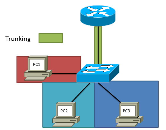
However a multilayered switch which has usually plenty of bandwidth on its back plane and would be able to handle this easily and in this example this would be a great use case to create and SVI interface for each network. To create an SVI:
We have to have a VLAN created first, in this example lets use 105.
switch(config)# vlan 105
switch(config-vlan)# name RED-NETWORK
switch(config-vlan)# exit switch(config)#
switch(config)# interface vlan 105
switch(config-if)# ip address 192.168.150.1 255.255.255.0
switch(config-if)# no shutdown
switch(config-if)# exit
switch(config)# interface ethernet 1/1
switch(config-if)# switchport
switch(config-if)# switchport mode access
switch(config-if)# switchport access vlan 105
switch(config-if)# no shutdown
switch(config-if)# exit
switch(config)# vlan 110
switch(config-vlan)# name TEAL-NETWORK
switch(config-vlan)# exit
switch(config)# interface vlan 110
switch(config-if)# ip address 192.168.160.1 255.255.255.0
switch(config-if)# no shutdown
switch(config-if)# exit
switch(config)# interface ethernet 1/2
switch(config-if)# switchport
switch(config-if)# switchport mode access
switch(config-if)# switchport access vlan 110
switch(config-if)# exit
switch# show ip route
IP Route Table for VRF "default"
'*' denotes best ucast next-hop
'**' denotes best mcast next-hop
'[x/y]' denotes [preference/metric]
'%' in via output denotes VRF

192.168.150.0/24, ubest/mbest: 1/0, attached
*via 192.168.150.1, Vlan105, [0/0], 00:06:03, direct
192.168.150.1/32, ubest/mbest: 1/0, attached
*via 192.168.150.1, Vlan105, [0/0], 00:06:03, local
192.168.160.0/24, ubest/mbest: 1/0, attached
*via 192.168.160.1, Vlan110, [0/0], 00:01:59, direct
192.168.160.1/32, ubest/mbest: 1/0, attached
*via 192.168.160.1, Vlan110, [0/0], 00:01:59, local

switch# show ip interface brief

IP Interface Status for VRF "default"(1)
Interface            IP Address      Interface Status
Vlan105              192.168.150.1   protocol-up/link-up/admin-up
Vlan110              192.168.160.1   protocol-up/link-up/admin-up
switch#
PC-2> ping 192.168.150.10
192.168.150.10 icmp_seq=1 timeout
192.168.150.10 icmp_seq=2 timeout
84 bytes from 192.168.150.10 icmp_seq=3 ttl=63 time=15.258 ms
84 bytes from 192.168.150.10 icmp_seq=4 ttl=63 time=19.669 ms
84 bytes from 192.168.150.10 icmp_seq=5 ttl=63 time=19.113 ms
PC-1> ping 192.168.160.10
84 bytes from 192.168.160.10 icmp_seq=1 ttl=63 time=17.825 ms
84 bytes from 192.168.160.10 icmp_seq=2 ttl=63 time=19.710 ms
84 bytes from 192.168.160.10 icmp_seq=3 ttl=63 time=18.503 ms
84 bytes from 192.168.160.10 icmp_seq=4 ttl=63 time=18.577 ms
84 bytes from 192.168.160.10 icmp_seq=5 ttl=63 time=9.817 ms
Go into the interface and turn off switchport and add an IP address
switch(config)# interface ethernet 1/4
switch(config-if)# no switchport
switch(config-if)# ip address 192.168.253.1 255.255.255.252
switch(config-if)# no shutdown
switch(config-if)# exit
switch(config)# interface ethernet 1/5
switch(config-if)# no switchport
switch(config-if)# ip add 192.168.253.5 255.255.255.252
switch(config-if)# no shutdown
switch(config-if)# exit
switch(config)# show ip interface brief

IP Interface Status for VRF "default"(1)
Interface            IP Address      Interface Status
Eth1/4               192.168.253.2   protocol-up/link-up/admin-up
Eth1/5               192.168.253.6   protocol-up/link-up/admin-up
switch(config)#
switch(config)# ping 192.168.253.1
PING 192.168.253.1 (192.168.253.1): 56 data bytes
64 bytes from 192.168.253.1: icmp_seq=0 ttl=254 time=1.368 ms
64 bytes from 192.168.253.1: icmp_seq=1 ttl=254 time=1.205 ms
64 bytes from 192.168.253.1: icmp_seq=2 ttl=254 time=2.099 ms
64 bytes from 192.168.253.1: icmp_seq=3 ttl=254 time=1.166 ms
64 bytes from 192.168.253.1: icmp_seq=4 ttl=254 time=1.353 ms

--- 192.168.253.1 ping statistics ---
5 packets transmitted, 5 packets received, 0.00% packet loss
round-trip min/avg/max = 1.166/1.438/2.099 ms
switch(config)# ping 192.168.253.5
PING 192.168.253.5 (192.168.253.5): 56 data bytes
64 bytes from 192.168.253.5: icmp_seq=0 ttl=254 time=1.45 ms
64 bytes from 192.168.253.5: icmp_seq=1 ttl=254 time=1.28 ms
64 bytes from 192.168.253.5: icmp_seq=2 ttl=254 time=0.995 ms
64 bytes from 192.168.253.5: icmp_seq=3 ttl=254 time=1.408 ms
64 bytes from 192.168.253.5: icmp_seq=4 ttl=254 time=1.303 ms

--- 192.168.253.5 ping statistics ---
5 packets transmitted, 5 packets received, 0.00% packet loss
round-trip min/avg/max = 0.995/1.287/1.45 ms
switch(config)#