Configure Router on a Stick
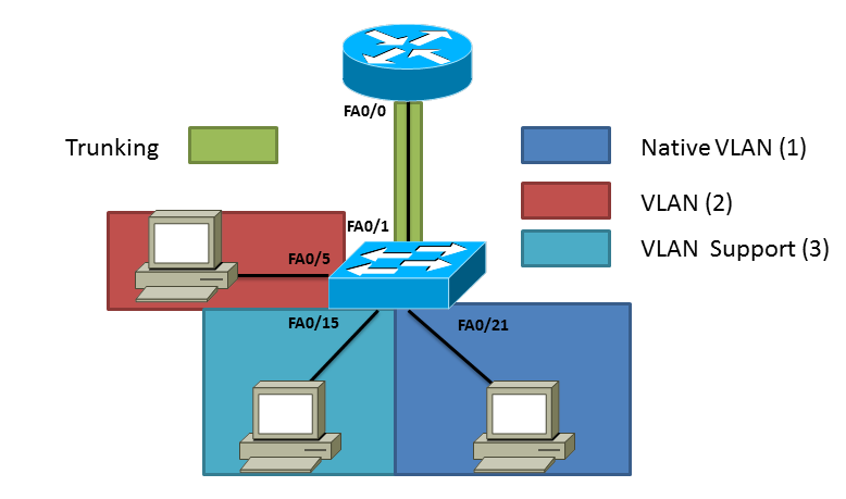
A while ago I talked about putting different VLANs on a switch, remember a VLAN is virtual network that although physically it may look like on the same network that does not always mean the case. By having VLANs you are segmenting the network and the only way to get to the other side is having a router. I have already configured the Cisco switch as posted in Creating VLANs but in summary I have three VLANs total VLAN 1 which is the native VLAN, VLAN 2 and VLAN 3 (which is called support. If you like to understand how create VLANs on a switch follow the post above. If you look at the network topology below you can see where Cisco came up with the name "Router on Stick" each PC is on its own network and needs the router in order for traffic to pass between the networks. Like before I have three VLANs total. VLAN 1 which is the native VLAN, VLAN 2 and VLAN 3 (which is called "Support").
You have to create sub-interfaces on the router to route between different VLANs these sub-interfaces do not correspond to the VLANs so you could put any number but for manageability usually people use the same sub-interface has the VLAN ID. To create a sub-interface start typing the interface that will be physically connected to the switch at the end add a period and number.
Router#config t
Enter configuration commands, one per line. End with CNTL/Z.
Router(config)#interface fastEthernet 0/0.2
Router(config-subif)#
Router(config-subif)#encapsulation dot1Q 2
Router(config-subif)#ip address 192.168.2.1 255.255.255.0
Router(config-subif)#no shut
Router#config t
Enter configuration commands, one per line. End with CNTL/Z.
Router(config)#interface fastEthernet 0/0.3
Router(config-subif)#
Router(config-subif)#encapsulation dot1Q 3
Router(config-subif)#ip address 192.168.3.1 255.255.255.0
Router(config-subif)#no shut
Router#config t
Enter configuration commands, one per line. End with CNTL/Z.
Router(config)#interface fastEthernet 0/0
Router(config-if)#ip address 192.168.1.1 255.255.255.0
Router(config-if)#no shut
Switch>en
Switch#config t
Enter configuration commands, one per line.  End with CNTL/Z.
Switch(config)#interface fastEthernet 0/1
Switch(config-if)#switchport mode trunk
Router#show ip route
Codes: C - connected, S - static, I - IGRP, R - RIP, M - mobile, B - BGP
       D - EIGRP, EX - EIGRP external, O - OSPF, IA - OSPF inter area
       N1 - OSPF NSSA external type 1, N2 - OSPF NSSA external type 2
       E1 - OSPF external type 1, E2 - OSPF external type 2, E - EGP
       i - IS-IS, L1 - IS-IS level-1, L2 - IS-IS level-2, ia - IS-IS inter area
       * - candidate default, U - per-user static route, o - ODR
       P - periodic downloaded static route

Gateway of last resort is not set

C    192.168.1.0/24 is directly connected, FastEthernet0/0
C    192.168.2.0/24 is directly connected, FastEthernet0/0.2
C    192.168.3.0/24 is directly connected, FastEthernet0/0.3
I hope this information is helpful I have also attached a PDF of the running-config of both devices to give you an example of the configuration. (Router-On-Stick-Example-RunConfig) If you have any questions post them below. Like always if you an idea of the next topic let me hear it.
Related articles
- OSPF...What a Protocol! (ryansrealm.com/ciscoskills)
- What is IPv6 ? An introduction to IPV6 (ipv6area.wordpress.com)
- Guest VLANS + Guest Wifi - Different IP Range, Out to Filtered Internet (edugeek.net)
- Journey to the CCIE LAB - Part 44 - BGP Link Bandwidth (mungauwamaseghe.wordpress.com)